Figure I. Schematic diagram of filter press
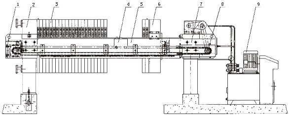
1,
passive sprocket components, 2, thrust plate
assembly, 3, plate assembly, 4, pull board manipulator,
5, main beam assembly, 6, pressed board assembly,
7, Cylinder Block, the total Cheng, 8, take the initiative to pull plate sprocket
components, 9, electric control hydraulic system.
Note: Picture shows the model to automatically pull plate models, non-automatic
pull-plate model without 1,4,8 parts. |